Charging and discharging of capacitors
A capacitor is a component that stores electrical energy in the form of an electric field.
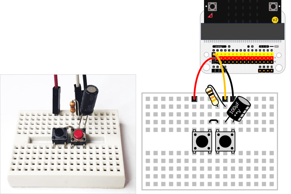
Assemble the capacitor and resistor on the breadboard, as shown below. When you press the charging switch on the left, you can measure the terminal voltage while charging. The jumper wire connects to pin 1 on the micro:bit.
If the above circuit is expressed as a general circuit diagram, it would look like the following figure.
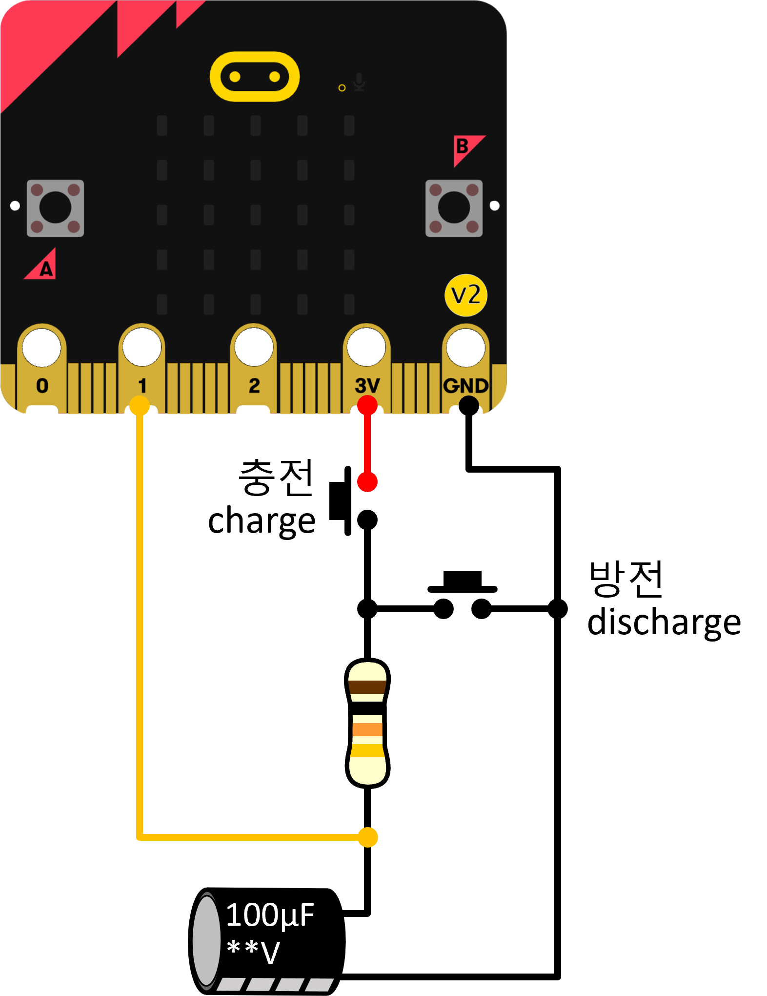
When you press the charging switch on the left, the current flows, and the capacitor is charged.
When the capacitor is fully charged, the current stops flowing, and the terminal voltage of the capacitor becomes equal to the supply voltage. This is because the voltage of the capacitor increases as more charges are accumulated.
When the discharge switch on the right is pressed, the capacitor is discharged through the resistor. As the charge stored in the capacitor is consumed, the terminal voltage of the capacitor converges to 0.
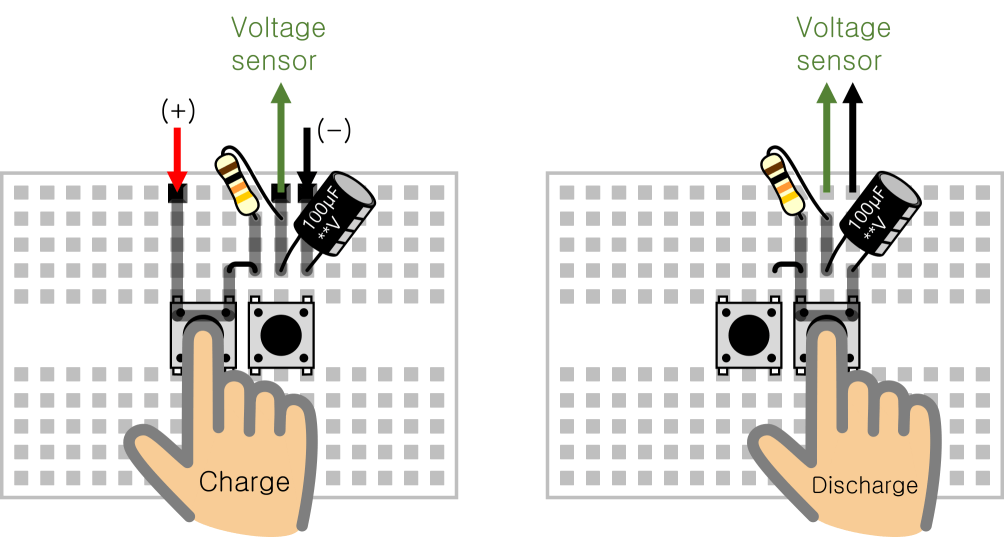
The charging and discharging process is represented by the path of current flowing through the breadboard, as shown in the following figure.
Tips
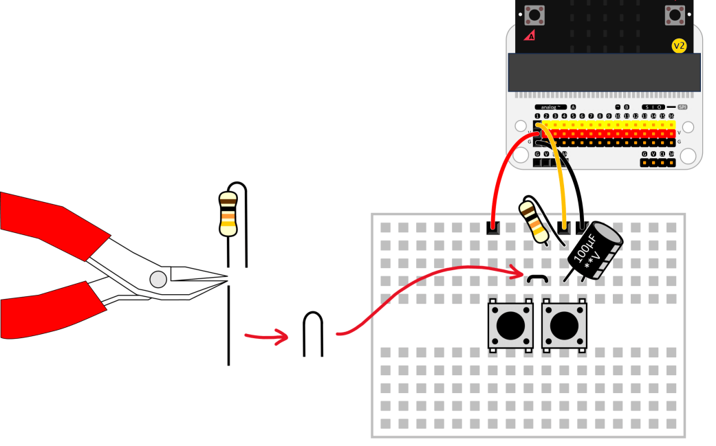
You can make jumper wire by recycling the resistor’s remaining leads. Check the picture below.
The jumper wire only needs to jump one step on the breadboard.
Note
Do not press the charge switch and the discharge switch at the same time. Pressing both switches at the same time will cause a short circuit in the power supply and reset the micro:bit system.
Capacitor charging and discharging experiment
- [Making a charge/discharge circuit] Assemble jumper wires, switches, resistors, and capacitors on the breadboard according to the instructions on the screen.
- Pairing to Micro:bit
- Press the discharge switch on the right sufficiently so that the terminal voltage of the capacitor becomes 0 V.
- Press the charging switch on the left to start charging. Measure and record the time it takes for the terminal voltage of the capacitor to rise to a specific voltage (e.g., 3 V).
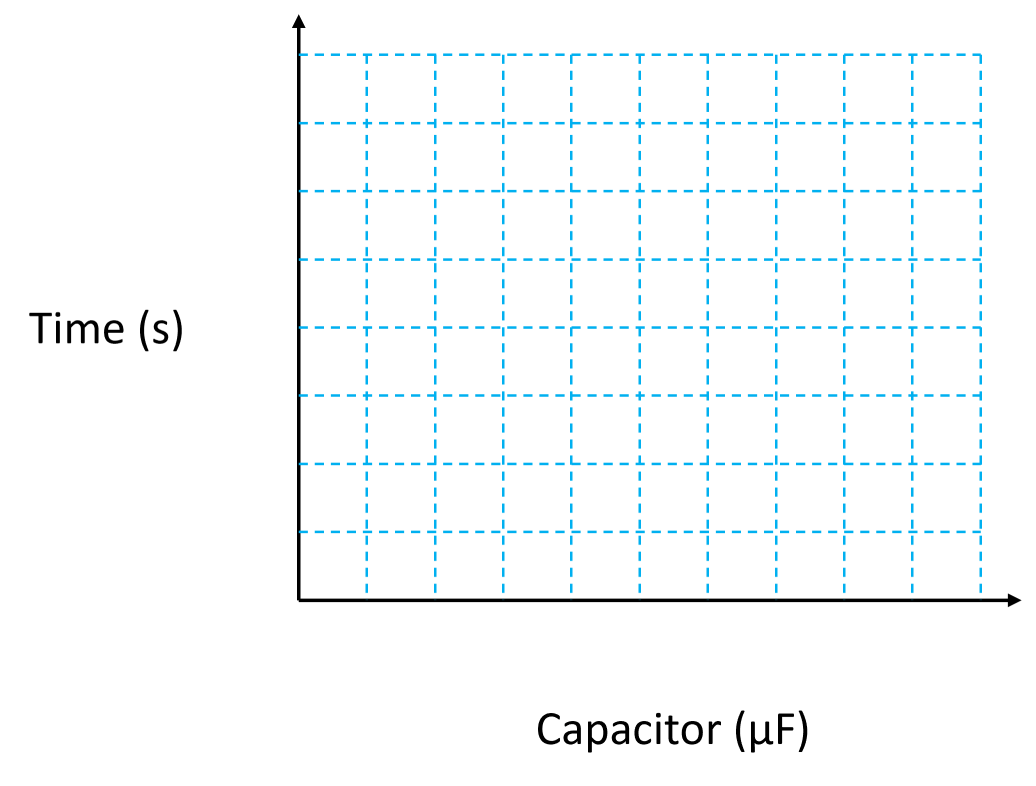
Capacitor The time it takes for the capacitor terminal voltage to rise from ( ) V to ( ) V (s). ( )μF ( )μF ( )μF - Plot the charging time on a graph.
- Look for trends in the graph.
