Multimeter
A multimeter is a measuring device that combines various measurement functions such as voltage, current, and resistance.
Multimeters are classified into analog and digital multimeters according to how they operate. Analog multimeters were used a lot in the past, with a moving needle pointing to the scale, but now they are rarely used. Most multimeters currently in use are digital.
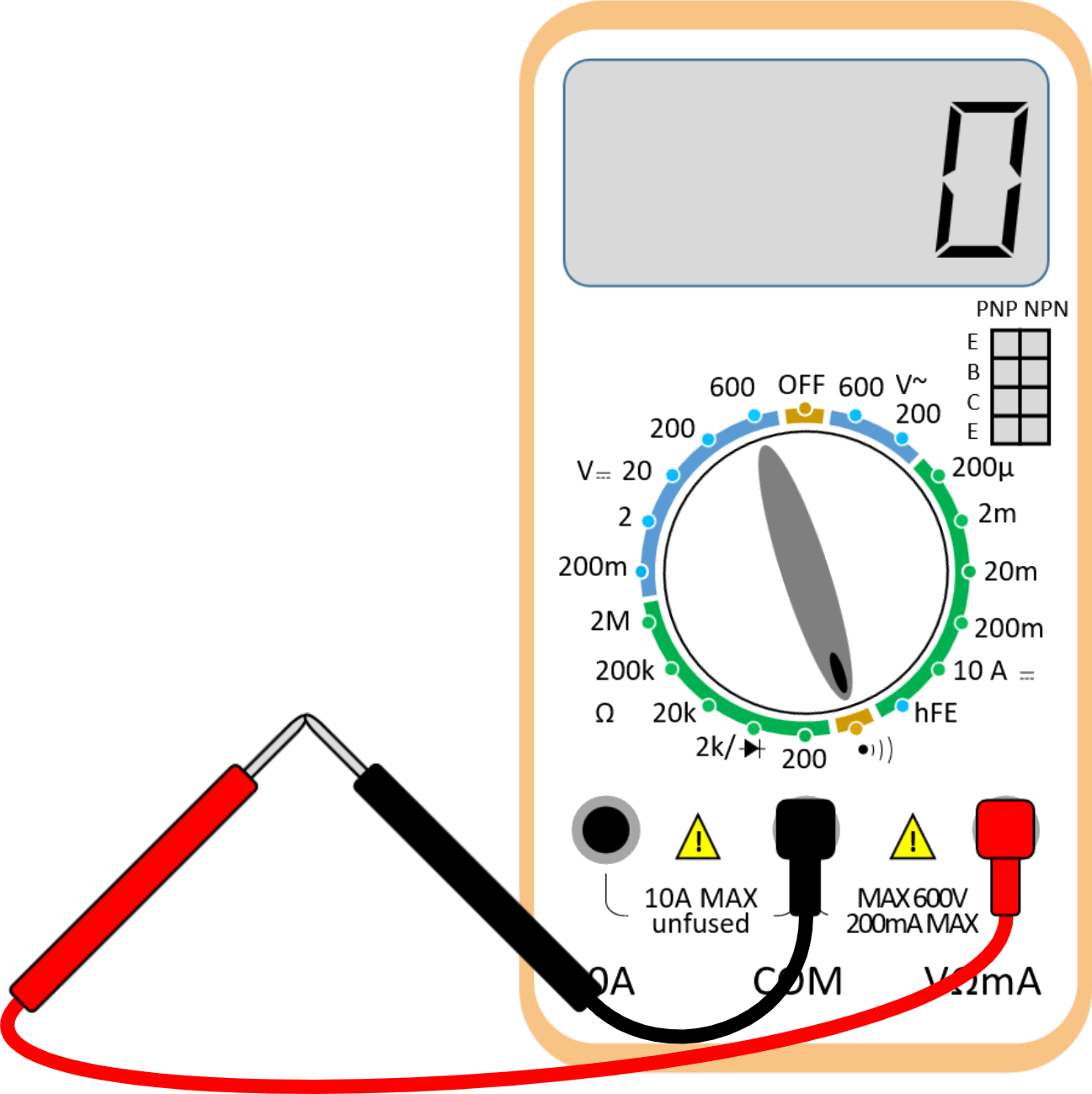
Terminals in multimeter
The terminals are where you connect the lead wires for measurement. The lead wire's red color represents the (+) pole, and the black color represents the (-) pole.
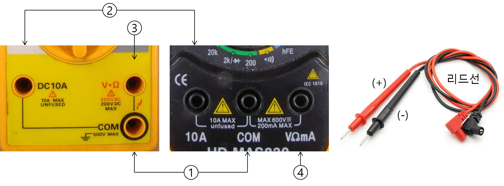
- COM : It means a common ground terminal. Connect the black lead wire.
- 10A : It is used to measure the current in the range of 0 to 10A. Connect the red lead wire.
- V•Ω : Used to measure voltage and resistance. Connect the red lead wire.
- VΩmA : You can measure voltage, resistance, and current in milliamps(mA). Connect the red lead wire.
Resistance measurement
The resistance can be measured by turning the rotary switch to the 'Ω' zone. The resistance value is measured by touching the lead wire to the resistance.
When measuring resistance, pay attention to the range. For example, if you measure a small value resistance in a large range, the measurement result will be '0'. Conversely, infinity (a '1' in the left corner) is displayed when the multimeter's measuring range is exceeded. Therefore, it is better to choose a range slightly larger than the expected resistance value. For example, if you measure a 10Ω resistance, it is appropriate to put the rotary switch range at 200.
Voltage measurement
Since DC voltage (DCV) and AC voltage (ACV) have different measurement mechanisms, it is necessary to turn the rotary switch well.
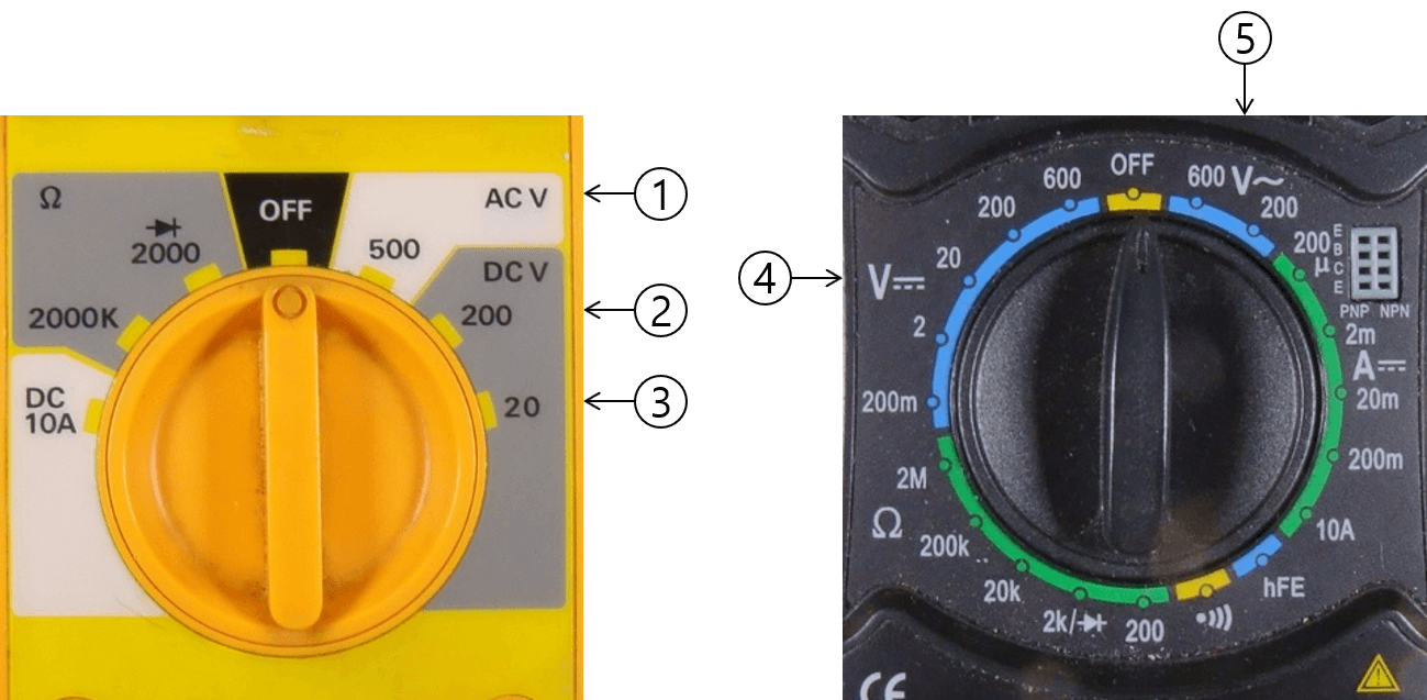
- ACV : AC voltage measurement
- DCV : DC voltage measurement
- 20 : Measure DC voltage from 0 to 20V
- V- : DC voltage measurement
- V~ : AC voltage measurement
DC current measurement

Current is a physical quantity different from voltage and refers to the amount of electric charge flowing through the wire per hour. Therefore, to measure the current, you must cut the wire to be measured. Some devices measure without cutting the wire.
There is one thing to be aware of when measuring current. During the current measurement, the resistance inside the multimeter becomes almost '0'. This is because the multimeter must not interfere with the flow of current. At this time, be careful because measuring the voltage of the battery or the like may cause overcurrent to flow and damage the multimeter. Some high-end multimeters have a protection circuit.
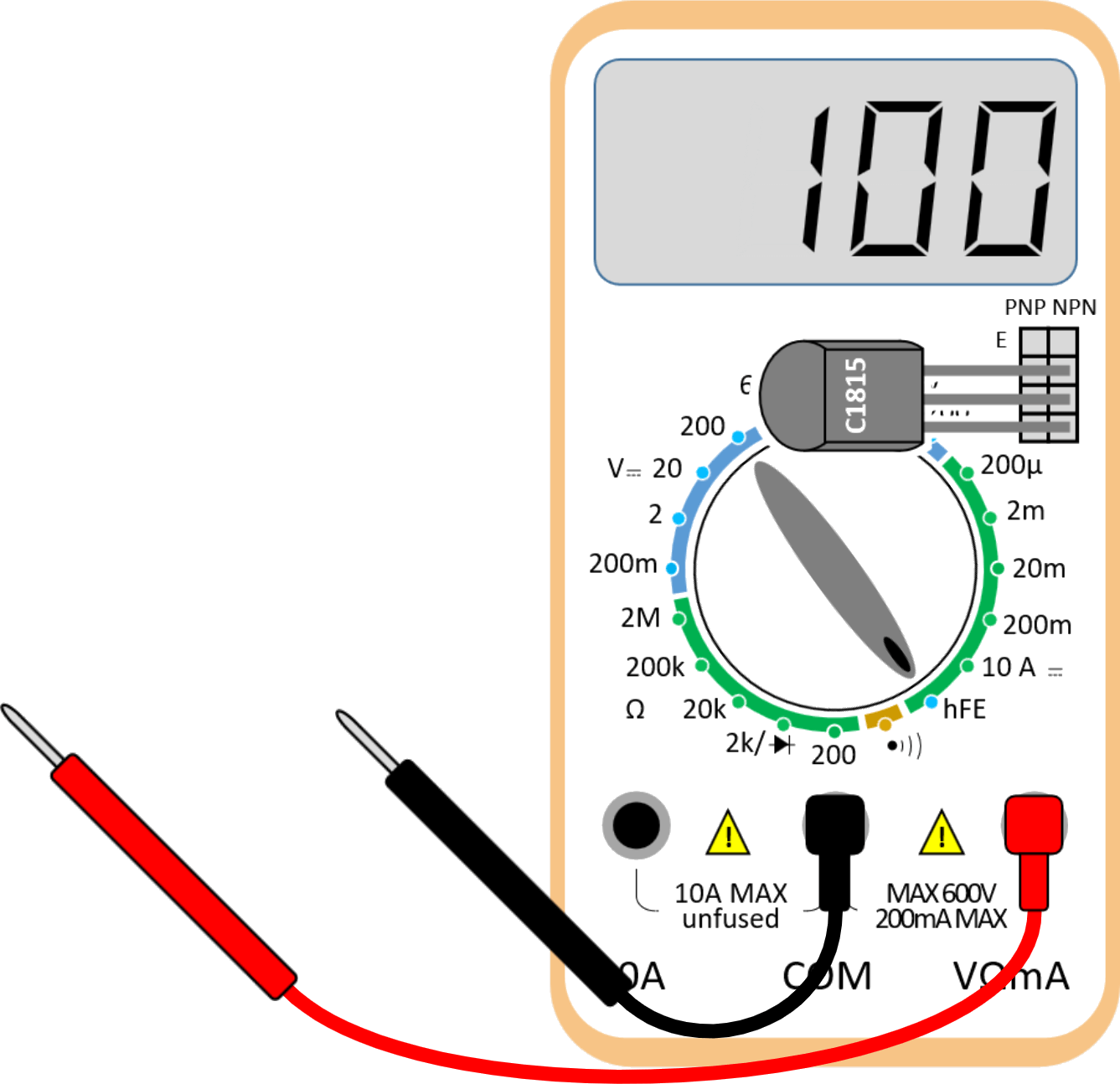
Transistor hFE measurement
The 'hFE' of a transistor is the collector (C) current ratio to the base (B) current. When the base current is '1', it tells how many times the collector current is amplified. hFE is also known as the 'current amplification factor.' When the transistor's three terminals are inserted, a number between about 50 and 200 is output. The output value is slightly different for each transistor.
Continuity test
This is a function to check whether the wires are connected. If the middle of the wire is not cut, a 'beep~' sound is output.